[Uni Tübingen] - [Mat.-Nat. Fakultät] - [Fachbereich Chemie] - [Anorg. Chemie] - [Klaus Eichele] - [NMR Ramblings] - [Processing] - DC Offset
 |
NMR Processing: |
Observation: the Fourier transformed FID shows a "peak" exactly in the middle of the spectrum (transmitter spike, o1 spike). Due to the nature of the Fourier transformation (all those integrals...) an effect that corresponds to one point in one domain will be caused by all points in the other domain. Here, it is a constant voltage offset of the real or imaginary part of the FID that causes this peak.
 |
This is a Cd-113{H-1} NMR spectrum, where I actually exaggerated the effect. |
How to recognize? One can observe the effect in the FID or the spectrum:
|
|
|
|
How to avoid? Basically, there are two strategies: do it before the measurement or after the measurement:
- calibrate the DC offset of the ADC channels
AQS Technical Manual with DRU Systems: on Bruker Avance II consoles, this calibration is frequency and receiver gain dependent (in steps of 2.5 MHz or 1 dB, respectively) - or, using your favourite processing software, perform an offset correction before Fourier transformation; typically, the software calculates the average value
of the last quarter of the real and imaginary part of the FID and subtracts this value.
This should be done before any other manipulations!
|
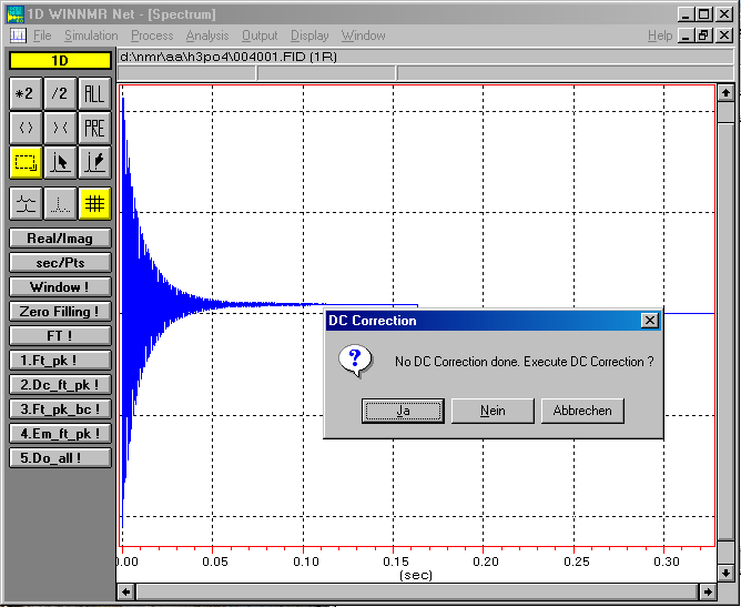
Comment: I thought this was a problem of the past, because DC offset correction has been around for decades. Users of Brukers WinNMR might remember how insistent WinNMR was on doing a DC offset correction. XWinNMR introduced the processing parameter BC_mod that defines the kind of DC offset correction. However, for digitally filtered FIDs (with AQ_mod=DQD, DQD = digital quadrature detection, a simultaneous mode that eliminates quad images and O1 spikes) this DC offset correction is not carried out, independent of the setting of BC_mod. We have noticed this particularly for spectra of heteronuclei that give not very strong signals and thus require many scans and long instrument times. Therefore, it is important to know how to get rid of this annoying feature! |
 |
Exercises: in order to illustrate the process of DC offset correction, I am providing two example data sets for download:
| the H-1 NMR spectrum of H3PO4 (a non-digitally filtered data set), | and the Cd-113{H-1} NMR spectrum of a cadmium tin complex (a digitally filtered data set). |
Non-digitally filtered data sets:
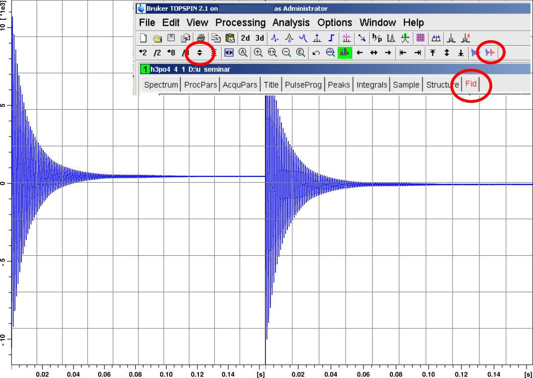
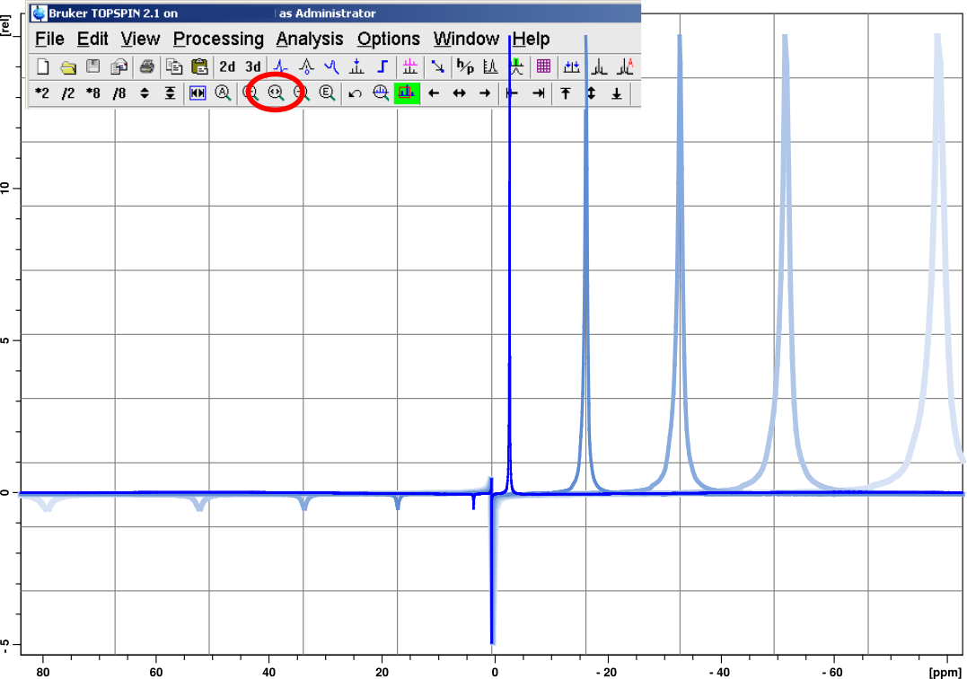
- First, verify the presence of the transmitter spike using the H3PO4 data set: carry out exponential multiplication (em), Fourier transformation (ft) and phase correction using the predefined phasing constants (pk). The result is a not so great, uncalibrated spectrum showing a broad peak at -2.6 ppm due to H3PO4, the dc offset artefact exactly in the center of the spectrum, and a quad image at 3.7 ppm.
- Now change the BC_mod parameter from none to quad
- Again, carry out em, ft and pk. Now the DC offset artefact is gone! If the BC_mod parameter is set to single or quad, the DC offset correction is performed automatically if you do em or ft or similar commands. If you want to see its effect separately, the command bc carries out the offset correction explicitly.
- As indicated, the correction procedure evaluates the last quarter of the FID. Thus, there could be a problem if the FID has not yet decayed to zero in this interval. You can simulate this behavior by telling the software to use a smaller part of the FID: set TDeff=4K and do em, ft, pk. The DC offset creeps back (in addition to effects due to clipping of the FID; you can remove the "wiggles" by adjusting the amount of zero-filling: SI=2K).
Digitally filtered data sets:
- First, verify the presence of the transmitter spike using the cadmium data set: carry out exponential multiplication (em), Fourier transformation (ft) and phase correction using the predefined phasing constants (pk).
- Under TopSpin, if AQ_mod=DQD, no baseline correction is performed, no matter whether BC_mod=single or quad. In order to force TopSpin to
perform a DC offset correction, you need to carry out user defined processing of raw data by issuing the command trf. This command will evaluate the
following parameters and act accordingly:
- baseline correction according to BC_mod (here: quad)
- linear prediction according to ME_mod (here: no)
- window multiplication according to WDW (here: em)
- Fourier transform according to FT_mod (here: fqc)
- phase correction according to PH_mod (here: pk)
In principle, digitally filtered data can be converted to analog data using the command convdta (use a different experiment number). However, TopSpin (2.1 pl 4) "forgets" to update the parameter AQ_mod to qsim. Therefore, you have to do it manually: "s AQ_mod qsim". Now you can treat the data set like a non-digitally filtered data set.
Correction Artefacts: Because the offset correction requires an evaluation of the end
of the FID, this cure may fail if the true signal has not decayed to zero yet (see point 4. of the
instructions for non-digitally filtered data sets). However, a curious example is the spectrum shown below:

This is the H-1 NMR spectrum of paramagnetic nickelocene. It is a digitally filtered data set.
With BC_mod=quad, any version of TopSpin (up to 4.4.1) will produce the central spike
after ft or trf. With BC_mod=none, TS 3 or 4 produce no central spike,
while TS 2 produces this artefact independent of BC_mod. Other, non-Bruker software, does not
create this artefact.
[ Anorg. Chemie ] | [ Go Home ] | webm@ster | last modified: 16.12.2024